Cambium Networks EasyPass

SMB, hospitality, and MDU deployments requiring cost-effective cloud-managed Wi-Fi.

EasyPass
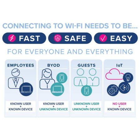
  • Specs: Cambium EasyPass combines security and simplicity, allowing guests and visitors to easily connect to the network on their own. BYOD users can securely self-onboard multiple devices, and employees can join the networking using their Microsoft or Google credentials.
  • Cambium EasyPass combines security and simplicity, allowing guests and visitors to easily connect to the network on their own.
  • BYOD users can securely self-onboard multiple devices, and employees can join the networking using their Microsoft or Google credentials.

Better pricing available. Our experts can help you secure the lowest rate on this model. Talk to an expert →

Request a Quote
  • Fast shipping — same-day processing before 4:15 pm PST
  • Authorized Reseller — Serving customers 20+ years
  • Call for Bulk Pricing

Sorry, this product is no longer available, please contact us for a replacement.


Click here to jump to more pricing!

Product Overview

Cambium Networks EasyPass

Cambium EasyPass combines security and simplicity, allowing guests and visitors to easily connect to the network on their own. BYOD users can securely self-onboard multiple devices, and employees can join the networking using their Microsoft or Google credentials.

Ideal Applications

SMB, hospitality, and MDU deployments requiring cost-effective cloud-managed Wi-Fi. MSP-managed networks leveraging cnMaestro for zero-touch provisioning and real-time monitoring.

Technical Details

Hardware Specifications

Comprehensive technical data for the EasyPass to ensure compatibility with your deployment.

Specifications

The Road to MassiveMU-MIMO .....................................................................................................3
MIMO Evolution...............................................................................................................................3
Towards MassiveMIMO ..................................................................................................................3
Benefitting MultipleSubscribers ...................................................................................................3
Spatial Multiplexing.........................................................................................................................4
Channel Sounding............................................................................................................................4
Putting it all Together.....................................................................................................................4
PMP 450m Overview........................................................................................................................5
Operating Modes.............................................................................................................................5
Advantages ofPMP 450m powered by cnMedusa .......................................................................6
Higher sector throughput...........................................................................................................................6
Range of sectorthroughput improvement ...............................................................................................6
Examples of MU-MIMOpatterns ...............................................................................................................7
Beamforming arraygain .............................................................................................................................8
Reduced interference..................................................................................................................................8
Additional antennatechnology advantages .............................................................................................9
Packet Per Second(PPS) processing capability .....................................................................................10
PMP 450m Limited....................................................................................................................................10
Comparison with802.11ac MU-MIMO feature ...........................................................................11
Networks today areat a crossroads. Outdoor fixed wireless access networks support highly cost-effective deployments
and bring high-speedconnectivity to hard-to-reach areas, but many network operators are facing challenges. They need to
enable denser subscribernetwork deployments per sector, and provide higher bandwidth to their subscribers, including
support for media-richservices such as IPTV or streaming video, with the goal of growing their average revenue per user
(ARPU) and future-proofingtheir networks.
Network operatorsalready deploying PMP 450 devices are challenged to achieve this leap in network capacity without
using more wirelessspectrum yet protecting their existing investments by avoiding wholesale replacements of the
networking equipmentalready deployed (e.g. a “forklift upgrade”).
Network operatorsplanning Greenfield deployments need to build a future-proof network, with the expectation that both
the number of subscribersand the usage per subscriber will increase significantly over time.
The Cambium NetworksPMP 450 platform, deployed worldwide as the basis for some of the largest fixed wireless access
service provider networksin the world, has evolved to meet these challenges with PMP 450m, powered by cnMedusa
technology – the industry’sfirst commercially deployed massive multi-user multiple-input multiple-output (MU-MIMO)
This white paper isan overview of the general technologies used in massive MU-MIMO, followed by specific details on
Cambium Networks’cnMedusa massive MU-MIMO technology as implemented in the PMP 450m product.
THE ROAD TO MASSIVEMU-MIMO
MIMO Evolution MIMOis a range of technologies used to multiply the capacity of a wireless connection without requiring
additional spectrum.At their most basic level, wireless communication systems can use a single antenna element to
communicate with eachother. This is known as a single polarization system.
By becoming a dualpolarization system - adding another antenna element to each wireless node - the network capacity
can be doubled withoutrequiring more spectrum by using the horizontal and vertical polarization of the radio wave, each
carrying a separatedata stream to transmit and receive data. Using vertical and horizonal polarizations is just an example
of dual polarizationsystems. Another example is using dual slant polarization, meaning at +45 degrees and -45 degrees.
PMP 450 is a dual polarizationsystem today.
This is also referredto as a 2x2 MIMO system, as both wireless nodes which are communicating with each other have
two antenna elements.The first number refers to the number of transmit antennas, the second to the number of receive
antennas used to communicateover the radio channel at any moment. Through the use of dual polarization antennas at
each end of the link,a 2x2 MIMO system can typically support two streams in the same radio spectrum.
Beyond dual polarizationsystems, MIMO techniques become more complex to implement. By adding more antenna
elements, the potentialcapacity gains increase but so does the signal processing and antenna design complexity.
Towards MassiveMIMO Systems that are greater than 8x8 MIMO systems are typically considered massive MIMO
systems. Massive MIMOsystems require a highly complex active antenna array and advanced signal processing to realise
the benefit of massiveMIMO capacity in real world conditions.
The vast majority ofmassive MIMO systems today are experiments in academic laboratories. It has proven very difficult for
wireless equipmentmanufacturers to create working, real world massive MIMO solutions. Current LTE and Wi-Fi standards
are showing increaseduse of MIMO techniques but have not yet achieved massive MIMO. Historically, MIMO technologies have been used to increase capacity between two
Benefitting MultipleSubscribers
wireless nodes. Thisbenefits one subscriber at a time, and if a subscriber is not able to use all the capacity enabled
by MIMO, the capacityis not utilized. Also, the increased capacity can be achieved only if the subscriber matches the
capability of the accesspoint (AP), meaning the same number of transmit and receive antennas.
As network operatorsaim for the highest utilization of their network possible, this is not ideal. A recent development is to
use these technologiesto allow an AP to communicate to several subscribers at once.
In traditional systems,each subscriber transmits or receives in sequence. If more than one subscriber were to transmit or
receive at the sametime, interference would occur between them, drastically limiting network performance.
MU-MIMO divides thecapacity of the antenna array used for MIMO between multiple subscribers, allowing multiple
subscribers to transmitand receive data concurrently. This allows the network operator to both increase network capacity
and better utilize thenetwork capacity. To benefit from MU-MIMO, the antenna array of the AP must be highly sophisticated. Resources are
allocated by the accesspoint to different subscribers by electrically tuning the antenna elements to different phases.
This technique is knownas beamforming, as the antennas used to communicate to a particular subscriber are tuned such
that their radio beamis targeted (or ‘formed’) to overlap a specific subscriber.
The goal of beamformingis to allow spatial multiplexing. This is the name given to making concurrent transmissions
possible in the samewireless spectrum by using physically separated radio beams.
By targeting a beamto a specific subscriber, the beam to each subscriber is much narrower than the beam from an AP
(in a conventional system,sectors are typically 90 or 120 degrees), multiple beams can then be used at once without them
overlapping to the extentthat would cause significant interference.
Beamforming can beapplied in both the uplink and downlink directions and has significant benefit to overall network
interference mitigationas well. This functionality does not require changes to the subscribers; only at the AP. PMP 450
subscribers alreadyuse directional (i.e. narrow) antennas to communicate to the AP. SM SM AP
Figure1 Figure 2 Figure 3
AntennaPattern for Beamforming to a Beamforming to seven
Sector ModeOperation single user users simultaneously
Channel SoundingThe access point must also be able to determine the state of the radio channel between it and each
subscriber. This is knownas channel state information (CSI). A complex channel sounding mechanism between the AP and
subscribers, occurringrapidly and continuously, must be used to ensure the most performance benefit is achieved.
The access point estimatesa property of the channel associated with each subscriber module (SM) called the spatial
frequency. This propertyof each SM channel is used by the spatial multiplexing and beamforming algorithms. The spatial
frequency is relatedto the azimuth angle of the subscriber, although the relationship is not unique (one-to-one).
Channel state informationis collected by the AP generating a test signal that is sent to a subscriber. The subscriber returns
the test signal, allowingthe AP to characterize the channel between the two radios. Using the channel estimate and the
spatial frequency itis possible for the AP to direct transmission to individual subscribers.
Putting it all TogetherThrough the combination of MIMO, spatial multiplexing through beamforming and highly efficient
channel sounding, amassive MU-MIMO system can be created. The first commercially available platform combining these
technologies is CambiumNetworks’ cnMedusa technology, first implemented in the PMP 450m product.
PMP 450m is an outdoorpoint-to-multipoint (PMP) AP incorporating cnMedusa technology. In the 5 GHz band, it has
a seven-element adaptivedual-polarity array smart antenna and massive MU-MIMO capabilities. The antenna array is
composed of fourteenchains, connected to seven vertical and seven horizontal antennas, covering 90 degrees in the
In the 3 GHz band, ithas a four-element adaptive dual-polarity array smart antenna. The antenna array is composed of
eight chains, connectedto four dual slant antennas, covering 90 degrees in the azimuth.
In both bands, the 90-degreeantenna can be used both in 90-degree sectors and in 120-degree sectors. In 90-degree
sectors, the antennagain at the edge of the sector is 3 dB lower than the peak value. In 120-degree sectors, the antenna
gain at the edge of thesector is 6 dB lower than the peak value.
Each PMP 450 SM operatesin 2x2 MIMO mode. In the 5 GHz band, the PMP 450m AP is capable of communicating with
up to 7 subscriberssimultaneously, supporting a total of up to 14 streams, making PMP 450m a 14x14 massive MU-MIMO
In the 3 GHz band, thePMP 450m AP is capable of communicating with up to 4 subscribers simultaneously, supporting a
The PMP 450m AP isinteroperable with PMP 450, PMP 450i and PMP 450b subscribers (referred to as PMP 450 series
The rest of this documentdescribes the PMP 450m AP in the 5 GHz band. All comments and descriptions apply also to the
3 GHz PM 450m, withthe only difference that eight chains are supported in the 3 GHz band, versus the fourteen chains in
The PMP 450m platformoffers great flexibility sustaining opportunities for future enhancements. It has quad core
processors, powerfulFPGA with 20 Gbps interface to processors, 14 flexible RF transceivers, and 2x5 Gbps fiber external
interface direct to theFPGA.
PMP 450m supportsmultiple communication modes, which will be described in detail in the rest of this document:
• Downlink Sectormode: used when transmitting
broadcast datato all subscribers, or unicast
data to an SMthat did not provide channel state
information. Functionallyequivalent to the mode
used by PMP450 and PMP 450i APs. • Downlink Beamforming mode: used when transmitting to one subscriber that provided channel state information. used when
• Downlink MU-MIMOmode:
transmittingto multiple subscribers that provided
channel stateinformation.
• Uplink Beamformingmode: used when receiving from one subscriber that provided channel state information.
• Uplink MU-MIMOmode: used when receiving from multiple subscribers that provided channel state information. used when receiving in contention (non-scheduled) symbols.
• Multiple fixed UplinkBeamforming mode:
ADVANTAGES OFPMP 450m POWERED BY cnMedusa
Higher sector throughputThe primary advantage of PMP 450m versus traditional 2x2-MIMO based APs, like the PMP
450 AP and the PMP450i AP, is the support of MU-MIMO mode, which multiplies the sector throughput.
Using the channel stateinformation each subscriber reports through the sounding mechanism, PMP 450m creates groups
of up to seven subscribers.Subscribers are selected for one of these groups based on their azimuth spacing and amount
of traffic, and their channelinformation is used to create up to seven spatially separated beams. Each beam points to one
SM in the group, andits nulls are aligned with the directions of the other subscribers in the group, limiting interference
Groups are createdevery TDD cycle (frame) based on current traffic and the latest RF conditions. Subscribers within a
group communicatewith the PMP 450m AP simultaneously, then (in the next symbol or in the next frame) the PMP 450m
creates a new groupand performs simultaneous communication with those subscribers. In ideal conditions, PMP 450m is
able to communicatewith seven subscribers simultaneously.
With cnMedusa, subscribersare unaware of the groups to which they belong. Consequently, there is no over the air
overhead or latencyassociated with group management.
Groups in the downlinkand uplink directions are independently created. Subscribers are selected to be part of a group in
one direction only basedon the traffic in that direction. A completely new group is then formed in the other direction.
Communicating withmultiple subscribers in the same channel at the same time provides a much higher sector capacity
without requiring morewireless spectrum, resulting in a dramatic increase in spectral efficiency. For an operator, this
means that a largernumber of subscribers can be supported in the sector in the same spectrum, or that existing
subscribers in the sectorcan experience higher average throughput.
The PMP 450m AP supportsa sector capacity of more than 900 Mbps in a 20 MHz channel and more than 1.3 Gbps in a 40
Range of sector throughputimprovement What is the realistic sector throughput improvement offered by the
cnMedusa technologyin PMP 450m? PMP 450m can communicate with up to seven subscribers in a group, but the
expected throughputimprovement is up to three times that of PMP 450 (or PMP 450i), depending on the specific
deployment. Factorsthat affect the actual sector throughput improvement are:
• The modulationlevel used for each subscriber in a group may be lower than the modulation level used when
communicatingto one subscriber only. This is due to residual interference between subscribers when forming beams
• In the default configuration,only lower priority traffic is grouped. Traffic on the higher priority data channels is
transmitted toone subscriber at a time in sector or beamforming mode, because typically the amount of information
transmitted athigher priority is small. It is preferable to group users that need a large amount of data, resulting in a
group that spansmore symbols and uses resources more efficiently. Operators have access to the selection of which
QoS levels outof the four offered for each SM can be grouped.
• Subscribers canbe grouped if they are sufficiently spaced in azimuth. Wider sectors with a large number of
subscribers uniformlydistributed in azimuth have a higher probability of creating large groups. This translates into
a higher probabilityof transmitting multiple streams, and therefore into a higher sector throughput. The azimuth
separation necessaryto group users is around 6-7 degrees.
• Subscribers canbe grouped if they have traffic to send/receive. Sectors that are very active have a higher probability
of finding subscribersthat can be grouped.
• Subscribers belowpeak of beam may be ineligible for MU-MIMO grouping if their channel distortion is too large.
These subscribersare very close to the access point and can typically support a high modulation mode in
non-MU-MIMOmode. However, when MU-MIMO mode cannot be used, the sector throughput doesn’t increase.
The best candidatefor a sector using cnMedusa with MU-MIMO mode enabled is a wide sector, with a large number of
subscribers, whichare fairly active, dispersed across the azimuth, do not have a large amount of high priority traffic and no
The cnMedusa technologyhas been optimized for simultaneously streaming data to and from many users such as video.
With the same frequencyreuse benefits as other PMP 450 series APs, spectral efficiency is the highest in any commercially
available system. Thespectral efficiency of the PMP 450m AP is up to 45 b/s/Hz in a sector and up to 90 b/s/Hz in a four-
sector deploymentwith back-to-back frequency reuse.
Given that in manydeployments spectrum is scarce, being able to increase capacity without having to increase the channel
bandwidth is a significantadvantage for the network operator. That these gains are achieved by only changing the AP
hardware is anothersignificant benefit.
Examples of MU-MIMOpatterns MU-MIMO patterns are generated frame by frame according to the SMs the PMP
450m AP needs to communicatewith.
Figure 3 shows someexamples of MU-MIMO composite patterns. The composite pattern is the overlap of the individual
beamforming patterns,each with a peak in the direction of one of the SMs in the group, and nulls in the direction of
the other SMs. Havingnulls in the direction of the other SMs in the group keeps the interference between concurrent
The overlapping beamsare calculated using information on the Spatial Frequency (azimuth) of the SM, and the channel
state information ofthe channel between the AP and each SM.
In the examples in Figure4, we see the AP with the SM’s (orange tirangles) oriented towards it, with four shades of blue per
beam in the coveragearea various modulation levels. From the darker shade of blue to the lighter, the modulations are
256-QAM, 64-QAM,26-QAM and QPSK. Figure 4 - Examples of MU-MIMO patterns
There are also numerousbenefits in using PMP 450m versus PMP 450 or PMP 450i AP, even if MU-MIMO is not enabled.
Beamforming arraygain If the MU-MIMO feature is not enabled, PMP 450m communicates to each individual SM in
beamforming mode.Using the channel state information provided by the subscriber through the sounding mechanism,
PMP 450m forms anarrow beam in the direction of the intended subscriber, therefore limiting interference to nearby
In EIRP limited regions,the transmit power needs to be decreased as the array gain increases, so that the total EIRP, given
by the sum of the transmitpower, the array gain, and the antenna gain, does not exceed the regulatory limit.
In these regions, withor without array gain, meaning in sector mode or in beamforming mode, the EIRP, and therefore the
link budget, is the sameas that of the PMP 450 or 450i.
By a combination ofinnovative RF and antenna design and unit calibration, cnMedusa determines the maximum EIRP for
each beam createdtaking into account array gains. This is used to determine a beam-specific Tx power backoff to ensure
all beams comply withthe EIRP limits for the configured region.
There is one advantage,however, in operating at reduced transmit power; when the radio operates far from the saturation
point of the power amplifier,in a more linear region, it is less subject to distortion and can more easily operate at higher
In non-EIRP limitedregions, the array-gain, in addition to the antenna gain, increases the EIRP and therefore the link
budget. This has theeffects of:
• Increasing therange.
• Increasing theaverage modulation level achieved by the subscribers, which increases the sector throughput in the
In the uplink direction,the array gain associated with the narrow beam increases the link budget, which means that each
subscriber can on averageachieve a higher modulation level. This translates in better sensitivity, and it increases the sector
throughput in the uplinkdirection.
Reduced interferenceThe narrow beams created in the downlink and uplink beamforming mode, as well as
MU-MIMO mode, notonly increase link budget, and therefore coverage and throughput, but they also reduce the system’s
In the downlink, whentransmitting in beamforming mode, interference is only created in the direction of the intended
subscribers. Any otherdevice operating on the same frequency in the same area will not suffer from interference due to
this transmission unlessit is located in the same direction. Compared to an AP that transmits in all directions in the sector,
as in a conventionalsystem, the interference created by PMP 450m is greatly reduced.
In the uplink direction,when receiving in beamforming mode, PMP 450m is only receiving (or ‘listening’) in a narrow beam
directed toward theintended subscriber. Any transmissions outside this beam are not received and cannot interfere with
the desired signal. Keepingthe interference level low using these techniques means that on average the subscribers can
achieve higher modulationlevels, which increases the uplink sector capacity and overall system efficiency.
Figure 5 shows an exampleof increased uplink throughput and reduced uplink interference using beamforming mode. Figure 5 - Example of uplink throughput and interference rejection improvement
The figure to the leftshows a typical sector deployment.
The AP receives transmissionsfrom one SM at a time. The modulation each SM uses for transmission depends on the SM’s
distance to the AP. Theblue shades show the areas where the SMs operate at progressively reduced modulation: 256-
QAM, 64-QAM, 16-QAMand QPSK. The SMs in the light blue region operate at the lowest modulation (QPSK).
The figure to the rightshows the same deployment, but with the AP operating in uplink beamforming mode.
The beam is now directedonly in the direction of the intended subscriber.
As the array gain ofthe antenna increases the link budget, the areas covered by higher modulation operation are
extended. The SM atthe edge of the coverage area, that was originally operating at QPSK modulation can now operate at
16-QAM modulation,doubling its throughput. The overall sector capacity is also improved when one SM’s link improves, as
SMs are served faster,and resources can be allocated to other SMs.
In addition to the benefitof link budget improvement, and therefore increased throughput, the interference rejection
capability of the APalso improves with uplink beamforming.
As the AP is typicallyinstalled in a high location, with visibility of a large area and possibly a large number of interfering
devices, it is more susceptibleto interference.
In the figure to the left,an interfering signal in the coverage area (red device) may corrupt the received signal coming from
any of the SMs in thecoverage area. This results in the SM having to operate at a lower modulation, therefore achieving a
In the figure to the right,only the signal coming from the direction of the transmitting SM is received at the AP. Any
interfering signal outsidethe narrow beam is rejected, and therefore does not affect reception of the signal. In this case
the modulation theSM operates at is not degraded, the SM’s throughput is higher, and the overall sector capacity is also
Additional antennatechnology advantages The PMP 450m AP is integrated with a sophisticated antenna array, which
in addition to supportingbeamforming, beam steering, and MU-MIMO functionality, has additional features which improve
The integrated antennahas a built-in 2-degree electrical down-tilt. Down-tilting the sector antenna is a common practice
because typically theAP is installed at higher elevation than the SMs. By down-tilting the antenna, more SMs are closer to
the peak of beam, andinterference to neighbouring sectors using the same frequency is decreased.
Any antenna can bemechanically down-tilted. But electrical down-tilt provides more control and better performance. The
difference is that withmechanical down-tilt the tilting angle is higher at boresight, but lower at the edge of the sector (at
+/- 45 degrees for a90-degree sector). This means that the positive effect of down-tilting peaks in front of the antenna but
decreases on the sides.On the other hand, electrical down-tilting allows the tilt to be uniform across the sector, and
therefore achieves betterperformance over the whole sector beam-width.
Additionally, the PMP450m antenna uses null-filling to improve performance for SMs located closer to the AP. A typical
sector antenna thatdoes not provide null-fill may have a pattern with deep nulls at close range. If SMs located close to the
AP fall into a null, theirreceived signal strength is greatly attenuated, causing the device to switch to a lower modulation
level, or drop the linkif the attenuation is too high. In mobile applications this is typically not a concern as the mobile
device can move aroundand as soon as it leaves the location of the null, the signal strength is significantly higher. However,
in a fixed deploymentthe subscriber is always in the same location; if the location happens to coincide with a null, the
reception would alwaysbe poor. This is why it is important for sector antennas in fixed deployment to have good null-fill
properties, like thePMP 450m AP antenna.
Both these antennafeatures benefit not only the single subscriber, which can receive a stronger signal and therefore
on average operateat a higher rate, but also all the other subscribers in the sector. Every device that can transfer data
faster uses fewer symbolsin the TDD frame and leaves resources available for other devices. The whole sector capacity is
therefore improvedby increasing performance in specific directions.
Packet Per Second(PPS) processing capability PMP 450m is an advanced platform with powerful processing
capabilities. This reflectsdirectly on the PPS, which measures the number of packets the device can process in a second.
A high PPS value allowsthe AP to sustain a very high sector throughput, even when processing a large number of small
packets such as thosefound in voice over IP (VoIP) and gaming applications. Correspondingly, a smaller PPS value limits
the sector throughputwhen a large number of small packets needs to be processed, as the device would not be able to
The PMP 450 AP hasa PPS processing capability of about 12k packets per second. The PMP 450i AP improved upon that
and has a PPS processingcapability of about 45k packets per second. The PMP 450m has a PPS processing capability of
200k packets per second,with potential software improvements that can push that number higher.
Regardless of the communicationmode (sector, beamforming or MU-MIMO), PMP 450m can sustain much higher
throughput when trafficis composed of a large number of small packets.
PMP 450m LimitedThe PMP 450m is available in two versions. The Full version with all the capabilities of cnMedusa, or a
Limited version thatrestricts operation of MU-MIMO. The simple application of a software license key can enable MU-
MIMO operation atany time. This allows a network operator to deploy the PMP 450m hardware at a lower cost, and update
to MU-MIMO operationat a later time. What are the advantages of purchasing a PMP 450m AP without the MU-MIMO
PMP 450m is designedfor sectors with very high capacity. However, some sectors may start with a small number of users,
with the potential ofmany more being added over time. If there is no need for very high capacity when the sector is first
installed, it is possibleto deploy the PMP 450m without the MU-MIMO feature enabled. As the sector grows and more
and more subscribersare added to the sector, the MU-MIMO feature can be enabled, allowing the AP to support a much
higher throughput withouthaving to change the hardware. This is a future-proof investment for sectors that are expected
to grow. This can beespecially useful if the AP deployment location is difficult or expensive to access.
Another benefit of thePMP 450m is in the interference reduction due to receive beamforming, as described earlier. This
function is inherentin the cnMedusa technology, and is present even in the Limited version.
PMP 450m Limitedis an option for smaller sectors to benefit in the future from high performance MU-MIMO functionality
when their sector hasscaled to an appropriate size, while offering a lower entry point cost than the full PMP 450m AP.
COMPARISON WITH802.11ac MU-MIMO FEATURE
The MU-MIMO featureis now part of many standards, like 802.11.
It was introduced ason optional feature in the 802.11ac standard, but it wasn’t included in the first generation of 802.11ac
devices. Newer devicesare now starting to incorporate the MU-MIMO feature, recognizing the great potential in capacity
increase given by thecapability of sending data to multiple devices at the same time.
Comparing the implementationof MU-MIMO in the PMP 450m AP and in an 802.11ac device, the first difference is that
802.11ac devices supportMU-MIMO only in the downlink direction, while the PMP 450m AP supports it both in the
downlink and in theuplink direction. Not supporting MU-MIMO in the uplink direction creates a double penalty.
The first is the obviousfact that the uplink capacity is not increased compared to when operating with SU-MIMO devices.
In deployments thatneed to support the uploading of large content files or two-way video conferencing, having MU-MIMO
only in the downlinkdirection does not necessarily improve the user experience.
The second is that theincreased capacity offered by MU-MIMO in the downlink direction is typically used to serve more
users, and more usersalso generate more uplink traffic. Now the system has more uplink traffic and no increased uplink
capacity, with the onlysolution to use more airtime in the uplink direction to accommodate the additional traffic. The
additional airtime neededin the uplink direction reduces the airtime in the downlink direction, which is the only one
benefitting from theMU-MIMO capacity increase.
The PMP 450m AP alsosupports uplink MU-MIMO transmissions for acknowledgments. These are the messages sent
from the subscribersto the access point, to acknowledge reception of downlink transmissions. If the access point is able
to receive multiple acknowledgmentsat the same time, more air time is left available for transmission of data, and this
increases the sectorcapacity even more.
The 802.11ac standardsupports MU-MIMO only up to 8x8, meaning eight streams, and the number of concurrent
subscribers receivingdata cannot exceed four. The PMP 450m AP supports up to 14 streams sent to up to seven
subscribers, with anobvious advantage in improved sector capacity.
Another differenceis in the sounding mechanism. The access point forms MU-MIMO groups to send data to multiple
subscribers at the sametime, and in order to create the beams in the exact direction of each subscriber, it needs to
have accurate channelstate information, reported by each subscriber through the sounding mechanism. Because the
information needs tobe accurate, the message from each subscriber to the access point may be large, and it needs to be
periodically repeatedto keep track of any changing condition in the channel. The 802.11ac standard is designed to support
mobility, where thechannel can greatly change from one sounding report to the next. Therefore, each sounding report
needs to carry informationon all subcarriers and all streams.
The PMP 450m soundingmechanism, however, is optimized for fixed wireless deployments, where channel conditions
are more stable. Thesounding report from each subscriber can be one of three formats: a long message, with accurate
channel state information,a compressed report for small changes in the channel, or no report if the channel has not
changed from the previoussounding exchange. This mechanism keeps the sounding overhead to a minimum, still allowing
the subscriber to quicklyreport any changes in channel conditions but saving uplink air time when no changes have
Finally, when groupingdata to multiple users, throughput is maximized if the length (in time) of the transmission is the
same for all the subscribersin the group. If users have different amount of data to receive, the sector capacity is increased
only for the amountof time data is actually sent to different users. The 802.11ac standard has less control over the length
of the transmissions,as one or more whole packets are sent in each transmission. The PMP 450m AP on the other hand
divides all transmissionsinto small fragments, and it has more control over the amount of data that can be grouped at a
PMP 450m is an APpowered by cnMedusa technology which allows a network operator to vastly increase sector capacity,
without requiring morewireless spectrum and while protecting current investment in PMP 450 subscribers.
MU-MIMO mode providesa large boost in sector capacity and incorporates highly advanced signal processing, antenna
array control and channelsounding techniques. Even if the operator does not operate PMP 450m in MU-MIMO mode,
beamforming and higherpacket processing capability provide a considerable performance benefit over PMP 450 and PMP
PMP 450m representsa significant technical leap over existing commercial fixed wireless access systems, allowing network
operators to futureproof their network for years to come with confidence.
Copyright © CambiumNetworks, Ltd. All Rights Reserved | 3800 Golf Road, Suite 360 | Rolling Meadows, IL 60008
Downloads

Documentation & Resources

Download datasheets and technical documentation for the EasyPass.

Data Sheet

Download PDF →

Need Help?

Talk to a Pro →

Pricing Notes:

  • Pricing and product availability subject to change without notice.